What is a speed sensor in a car? Modern vehicles contain a variety of different speed sensors. For example, most cars have a vehicle speed sensor and multiple wheel speed sensors. Other types of sensors, such as the crankshaft position sensors and camshaft position sensors, are also technically speed sensors, even if they aren’t referred to as such.
What is a Speed Sensor?
The Society of Automotive Engineers (SAE) defines a speed sensor as a device that measures the number of revolutions or distance traveled per unit of time. One or more onboard computers (also known as control modules) receive data from the speed sensors. The modules then use the information to determine the operation of various output devices.
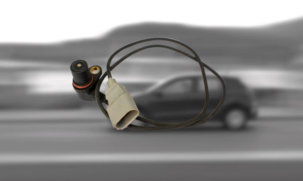
One example is the vehicle speed sensor (VSS). You might be wondering, “what does a speed sensor do?” As you probably guessed, the control module monitors the VSS signal to detect how fast the vehicle is traveling. The module then uses that data to determine the control of devices, such as the transmission shift solenoids and the speedometer. Without speed sensors, your speedometer and automatic transmission will likely run into issues.
Most of the time, the VSS is located on the transmission output shaft. As such, the VSS may also be referred to as an output shaft speed sensor. Some vehicles use both an input and output shaft speed sensor to monitor transmission operation.
Wheel speed input is typically used for vehicle dynamics purposes such as anti-lock brakes, stability control, and traction control among others.
How Does the Speed Sensor Work?
Like any other speed sensor, a speed sensor can be an inductive sensor (magnet with a wire coil surrounding it) that produces an AC analog wave, or it can be digital, which produces a square wave. Some wheel speed sensors are designed to detect whether the vehicle is moving forward or backward.
The sensor typically either reads steel teeth moving past the sensor as the wheel spins (this is very common) or in some cases, a series of small, carefully spaced magnets will be embedded in the bearing seal and the sensor will be designed to read those magnetic pulses.
Wheel speed sensors (WSS) are another example of an automotive speed sensor. The anti-lock brake (ABS) module monitors each wheel’s speed via the sensors. During an emergency braking situation, the module uses the data to determine when to pulse hydraulic pressure to the brakes, thereby preventing wheel lockup.

What Is the Difference Between Input and Output Speed Sensors?
As mentioned, some transmissions use two speed sensors to change gears accurately and adjust the torque converter.
To achieve ideal transmission performance, these two sensors have to fulfill their functions. Here’s the difference between the input and output shaft speed sensors:

Input Shaft Speed Sensor or ISS
Because it’s located near the turbine of the torque converter, this transmission speed sensor can also bear the name “turbine speed sensor.”
This is used to track the speed of the input shaft.
Output Shaft Speed Sensor or OSS
The output shaft detects the speed of the transmission output shaft.
Intermediate Shaft
Some linear automatic transmissions will have a sensor reading the speed of the intermediate shaft in the transmission.

Where are Speed Sensors Located?
In simple terms, the ISS sits on the front-end part of the transmission near the torque converter, while the OSS sits near the rear of the transmission.
The computer compares the data from these two sensors to make adjustments in the transmission’s operation and to detect internal transmission problems.
How Speed Sensors Work
Although the various speed sensors found throughout your vehicle serve different purposes, they all work in a similar fashion. All speed sensors read a reluctor wheel or exciter ring that is mounted to whatever rotating device is being monitored, but the method for reading the reluctor often varies.
Three Types of Wheel Speed Sensors
Variable Reluctance
Variable reluctance sensors are considered “passive” because they create their own voltage. When the teeth of the reluctor wheel passes in front of the sensor, it creates a voltage signal that is sent to the control module.
Hall-Effect
Hall-effect sensors are considered “active” sensors because they require an external electrical source to operate. These wheel speed sensors contain an integrated circuit and receive a reference voltage from the control module. When the reluctor wheel passes by the hall-effect sensor, it excites the integrated circuit inside to create the necessary signal.
Magneto-Resistive
Magneto-resistive sensors are also considered “active” sensors, plus they contain an integrated circuit—this means that they operate much like hall-effect sensors.
The primary difference is, this design can detect direction as well as speed.
Products Mentioned in this Guide
Any information provided on this Website is for informational purposes only and is not intended to replace consultation with a professional mechanic. The accuracy and timeliness of the information may change from the time of publication.


 Camshaft Position Sensor
 Crankshaft Position Sensor
 Speed Sensor
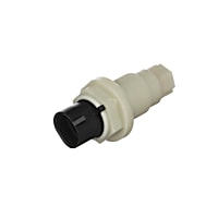 Automatic Transmission Input Shaft Speed Sensor
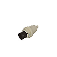 Automatic Transmission Output Shaft Speed Sensor


